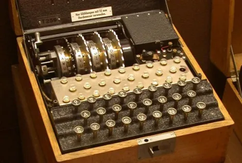
An Enigma cipher machine built with nothing but AND, OR, NOT gates and four T flip-flops. No arithmetic operators, no behavioural VHDL, every equation derived by hand from truth tables and Karnaugh maps. It ciphers digits (0 to 9) instead of letters, and just like the real machine it is self-inverse: put the ciphered value back in with the same settings and your original message comes out.
- 0-9 alphabet (4-bit BCD)
- 6 pipeline stages
- 5 automated test suites
- 241 exhaustive checks, all passing
- 9 years a bug stayed hidden
How it works, in one picture
Every keypress pushes a value through six stages. The counter is what replaces the rotating drum of a real Enigma, it steps by one after each keypress, so the wiring effectively shifts as you type. Type the digit 7 ten times in a row and you get 8, 6, 1, 3, 8, 6, 3, 8, 6, 1. Never the same value twice in a row, and never a 7.
          ┌─ counter c (0-9), steps on every keypress ─┐
          │                                            │
          ▼                                            ▼
input ─► adder ─► rotor ─► reflector ─► inverse rotor ─► subtractor ─► output
        (m+c)%10    R          Ref            Ri            (i−c)%10
A worked example
Let’s cipher the digit 3 with the counter sitting at 9, and then feed the result straight back in with the counter at 9 again:
| Stage | Encrypting | Decrypting |
|---|---|---|
| input | 3 | 2 |
adder (m+9)%10 | 2 | 1 |
rotor R | 6 | 3 |
reflector Ref | 3 | 6 |
inverse rotor Ri | 1 | 2 |
subtractor (i−9)%10 | 2 | 3 |
Same circuit, same settings, and the message comes back. There is no decrypt mode anywhere in the design, that symmetry just falls out of the maths, and it is the one property the whole test suite is built around.
The short version of the story
I wrote this in 2017 for a Digital Electronics course at university. It was submitted, demonstrated, graded, and I reopened the files every couple of years without ever suspecting there was anything wrong with it. Nine years later I wrote a proper automated testbench for it, mostly out of habit from my current job, and the cipher turned out to be broken. 80 of the 100 possible input combinations failed. The only ones that worked were the twenty or so I had happened to look at back in 2017.
Two separate bugs: eight wrong entries in a Karnaugh map I had derived by hand, and a missing subtractor that stopped the machine from being self-inverse. Both are explained further down, together with the gate-level design they were hiding in.
Details
Everything below is optional reading, open whatever you are curious about.
How a keypress travels through the machine The six stages and what each one does to the value
1. The counter, a rotor with no moving parts
A real Enigma rotor physically turns one step per keypress, which shifts the wiring by one position. Here that is a modulo-10 counter built out of four T flip-flops. Its value gets added to the input, which produces the same shifting effect with nothing actually moving.
2. The adder: (m + c) mod 10
Shifts the message by the counter position. If the sum goes over 9 it wraps around, so 8 + 5 comes out as 3.
3. The rotor, a fixed scramble
A combinational circuit that permutes the ten possible values. This is the internal wiring of the rotor drum:
| in | 0 | 1 | 2 | 3 | 4 | 5 | 6 | 7 | 8 | 9 |
|---|---|---|---|---|---|---|---|---|---|---|
R(x) | 2 | 3 | 6 | 8 | 0 | 9 | 7 | 4 | 5 | 1 |
4. The reflector, sending the current back
In the real machine the reflector bounces the electrical signal back through the rotors along a
different path. Here it is just the complement, Ref(x) = 9 − x:
| in | 0 | 1 | 2 | 3 | 4 | 5 | 6 | 7 | 8 | 9 |
|---|---|---|---|---|---|---|---|---|---|---|
Ref(x) | 9 | 8 | 7 | 6 | 5 | 4 | 3 | 2 | 1 | 0 |
Notice that no value maps to itself. That is the defining property of an Enigma reflector, and it is also the historical weakness that let Bletchley Park break the machine: a letter can never encipher to itself, which hands the codebreaker a free constraint on every single guess.
5. The inverse rotor, the return path
The current comes back out through the same wiring, so this block undoes the rotor exactly,
Ri = R⁻¹.
| in | 0 | 1 | 2 | 3 | 4 | 5 | 6 | 7 | 8 | 9 |
|---|---|---|---|---|---|---|---|---|---|---|
Ri(x) | 4 | 9 | 0 | 1 | 7 | 8 | 2 | 6 | 3 | 5 |
6. The subtractor: (i − c) mod 10
Takes out the shift the adder put in. This is the block that was missing from the original 2017 design, and not having it is what broke the cipher for every counter position except zero.
Why encrypting twice gives you the message back The one bit of maths the whole design rests on
Call the middle three stages g = Ri ∘ Ref ∘ R. The whole machine is then:
output(m, c) = ( g((m + c) mod 10) − c ) mod 10g is an involution, meaning that applying it twice gets you back where you started,
g(g(x)) = x. That happens because the reflector is symmetric and the return path
undoes the outward path exactly. So if you feed the output back in:
output(output(m, c), c)
  = ( g( ((g((m+c)%10) − c)%10 + c) %10 ) − c ) %10
  = ( g( g((m+c)%10) ) − c ) %10        the −c and +c cancel
  = ( (m+c)%10 − c ) %10                because g is an involution
  = m                                   ✓
Both cancellations are doing work there. Take the subtractor away and the middle line stops
collapsing, because g is not linear with respect to modulo-10 addition, so the counter
shift leaks through the permutation and never comes back out. That is bug 2.
The BCD counter: four T flip-flops State table, excitation equations and Karnaugh maps
A T flip-flop toggles when T = 1 and holds when T = 0, so
Qnext = Q ⊕ T. To design the counter you write down the state it has to
move to next, and then read off the toggles you need to get there,
T = Q ⊕ Qnext.
| state | Q3 | Q2 | Q1 | Q0 | next | T3 | T2 | T1 | T0 |
|---|---|---|---|---|---|---|---|---|---|
| 0 | 0 | 0 | 0 | 0 | 1 | 0 | 0 | 0 | 1 |
| 1 | 0 | 0 | 0 | 1 | 2 | 0 | 0 | 1 | 1 |
| 2 | 0 | 0 | 1 | 0 | 3 | 0 | 0 | 0 | 1 |
| 3 | 0 | 0 | 1 | 1 | 4 | 0 | 1 | 1 | 1 |
| 4 | 0 | 1 | 0 | 0 | 5 | 0 | 0 | 0 | 1 |
| 5 | 0 | 1 | 0 | 1 | 6 | 0 | 0 | 1 | 1 |
| 6 | 0 | 1 | 1 | 0 | 7 | 0 | 0 | 0 | 1 |
| 7 | 0 | 1 | 1 | 1 | 8 | 1 | 1 | 1 | 1 |
| 8 | 1 | 0 | 0 | 0 | 9 | 0 | 0 | 0 | 1 |
| 9 | 1 | 0 | 0 | 1 | 0 | 1 | 0 | 0 | 1 |
States 10 to 15 never happen, so they are don't cares (X). They can be whatever is
convenient, which lets the Karnaugh maps simplify a lot further than they otherwise could.
| Q3Q2\Q1Q0 | 00 | 01 | 11 | 10 |
|---|---|---|---|---|
| 00 | 0 | 0 | 0 | 0 |
| 01 | 0 | 0 | 1 | 0 |
| 11 | X | X | X | X |
| 10 | 0 | 1 | X | X |
| Q3Q2\Q1Q0 | 00 | 01 | 11 | 10 |
|---|---|---|---|---|
| 00 | 0 | 0 | 1 | 0 |
| 01 | 0 | 0 | 1 | 0 |
| 11 | X | X | X | X |
| 10 | 0 | 0 | X | X |
| Q3Q2\Q1Q0 | 00 | 01 | 11 | 10 |
|---|---|---|---|---|
| 00 | 0 | 1 | 1 | 0 |
| 01 | 0 | 1 | 1 | 0 |
| 11 | X | X | X | X |
| 10 | 0 | 0 | X | X |
T0 is 1 in every cell, the least significant bit toggles on every single clock.
Grouping the ones in the other three maps gives:
T3 = Q3·Q0 + Q2·Q1·Q0
T2 = Q1·Q0
T1 = Q3'·Q0
T0 = 1
T1 = Q3'·Q0 is where the decimal wrap lives. Bit 1 would normally toggle every
second count, but the Q3' term kills it at state 9, so the counter jumps back to 0
instead of carrying on to 10.
Gate-level design: Karnaugh maps for the rotor From a permutation table to four SOP equations, by hand
The rotor is a lookup table, but expressed as gates instead of memory. Each of the four output
bits is its own boolean function of the four input bits, so the permutation table turns into four
separate Karnaugh maps. Writing R(x) out in binary:
| in | s3 | s2 | s1 | s0 | out | r3 | r2 | r1 | r0 |
|---|---|---|---|---|---|---|---|---|---|
| 0 | 0 | 0 | 0 | 0 | 2 | 0 | 0 | 1 | 0 |
| 1 | 0 | 0 | 0 | 1 | 3 | 0 | 0 | 1 | 1 |
| 2 | 0 | 0 | 1 | 0 | 6 | 0 | 1 | 1 | 0 |
| 3 | 0 | 0 | 1 | 1 | 8 | 1 | 0 | 0 | 0 |
| 4 | 0 | 1 | 0 | 0 | 0 | 0 | 0 | 0 | 0 |
| 5 | 0 | 1 | 0 | 1 | 9 | 1 | 0 | 0 | 1 |
| 6 | 0 | 1 | 1 | 0 | 7 | 0 | 1 | 1 | 1 |
| 7 | 0 | 1 | 1 | 1 | 4 | 0 | 1 | 0 | 0 |
| 8 | 1 | 0 | 0 | 0 | 5 | 0 | 1 | 0 | 1 |
| 9 | 1 | 0 | 0 | 1 | 1 | 0 | 0 | 0 | 1 |
Four maps, one per output bit. Rows are s3s2 and columns are s1s0,
both in Gray code order so that neighbouring cells only differ by one bit. That is the trick that
makes the whole thing work: if two adjacent cells are both 1 you can group them, and the variable
that changes between them drops out of the term.
| s3s2\s1s0 | 00 | 01 | 11 | 10 |
|---|---|---|---|---|
| 00 | 0 | 0 | 1 | 0 |
| 01 | 0 | 1 | 0 | 0 |
| 11 | X | X | X | X |
| 10 | 0 | 0 | X | X |
| s3s2\s1s0 | 00 | 01 | 11 | 10 |
|---|---|---|---|---|
| 00 | 0 | 0 | 0 | 1 |
| 01 | 0 | 0 | 1 | 1 |
| 11 | X | X | X | X |
| 10 | 1 | 0 | X | X |
| s3s2\s1s0 | 00 | 01 | 11 | 10 |
|---|---|---|---|---|
| 00 | 1 | 1 | 0 | 1 |
| 01 | 0 | 0 | 0 | 1 |
| 11 | X | X | X | X |
| 10 | 0 | 0 | X | X |
| s3s2\s1s0 | 00 | 01 | 11 | 10 |
|---|---|---|---|---|
| 00 | 0 | 1 | 0 | 0 |
| 01 | 0 | 1 | 0 | 1 |
| 11 | X | X | X | X |
| 10 | 1 | 1 | X | X |
Grouping each map gives the sum of products form that goes straight into VHDL:
r3 = s2·s1'·s0 + s2'·s1·s0
r2 = s1·s0' + s2·s1 + s3·s1'·s0'
r1 = s3'·s2'·s1' + s1·s0'
r0 = s1'·s0 + s2·s1·s0' + s3·s2'
And in the source, one concurrent assignment per bit, four lines of VHDL that synthesise down to a couple of dozen gates:
rot3 <= (sum2 and not sum1 and sum0) or (not sum2 and sum1 and sum0);
rot2 <= (sum1 and not sum0) or (sum2 and sum1) or (sum3 and not sum1 and not sum0);
rot1 <= (not sum3 and not sum2 and not sum1) or (sum1 and not sum0);
rot0 <= (not sum1 and sum0) or (sum2 and sum1 and not sum0) or (sum3 and not sum2);
The reflector and the inverse rotor come out of exactly the same process. The reflector
collapses nicely because 9 − x is very regular:
ref3 = r3'·r2'·r1'
ref2 = r3'·r2'·r1 + r3'·r2·r1'
ref1 = r3'·r1
ref0 = r3'·r0' + r2'·r1'·r0
Do all of this by hand for twelve output bits and you have around a hundred terms to group and transcribe without slipping once. That is where bug 1 came from.
The bug that stayed hidden for nine years Two of them actually, one arithmetic and one architectural
Test 1 passed straight away, the reflector has no fixed points across all 100 cases. Test 2 failed badly, 80 out of 100 combinations broke the self-inverse property. The twenty that passed were all at counter position 0, which is exactly where my 2017 manual test cases happened to be.
Bug 1: eight wrong entries in the adder
The modulo-10 adder had 8 wrong entries out of 100 in its hand-derived SOP equations, three in bit 3, five in bit 2, none in bits 1 and 0. Karnaugh maps are a visual technique, and with around a hundred terms to group across four maps, misreading a few cells is almost inevitable. What made it invisible is that the errors only show up when the counter is not zero, and at counter 0 the adder is just the identity function, which is the only case anybody had checked.
Bug 2: a missing subtractor
The counter was added to the input before the rotor but never subtracted from the output. A real Enigma shifts the whole permutation by the rotor position, and adding a constant on the way in is not the same operation, so the difference does not cancel. Even with a perfectly correct adder the machine could not have been self-inverse for any counter other than zero. The fix is a modulo-10 subtractor after the inverse rotor.
Both are fixed now. The adder and the subtractor use compact ieee.numeric_std
processes instead of hand-derived equations, while the rotor, reflector and inverse rotor stay as
gate-level logic, since those are the part the exercise was actually about.
The automated test suite Five properties, and what each one can actually catch
The suite checks properties rather than hardcoded vectors, so it says something about the design instead of just pinning down whatever it happens to do today:
| Test | Property | Cases |
|---|---|---|
| 1 | The reflector never maps a value to itself | 100 |
| 2 | decode(encode(m)) == m for every counter position | 100 |
| 3 | The BCD counter walks 0-9 and wraps back to 0 | 11 |
| 4 | Rotor and reflector are permutations, and Ref(x) = 9 − x | 20 |
| 5 | The inverse rotor really inverts the rotor, R(Ri(y)) == y | 10 |
Tests 3 to 5 came later, and test 3 justified itself immediately. I checked the suite by deliberately breaking the design in three different ways, and a corrupted counter flip-flop walked straight past tests 1 and 2. Both of them set up the same broken counter on the encrypt pass and on the decrypt pass, so the symmetry still holds perfectly, it just holds around the wrong value. Only an independent check of the counter's own state sequence catches that. A round trip test that is self-consistent has a blind spot exactly where both directions share a component, which is something I had not really thought about before.
Methodology
The suite runs in GHDL. The stimulus process drives the clock itself, one pulse at a time,
instead of using a free running generator, because otherwise a clock edge can land in the middle of
a measurement window and the counter advances behind your back, which made the results
non-deterministic. Bus reads reject 'U' and 'X' outright instead of
quietly treating them as zero, so a test cannot pass on uninitialised garbage. Pass or fail is
decided by assert statements, and the run exits non-zero if any of them trips.
Test 1: PASSED (100 cases, no fixed points)
Test 2: PASSED (100 cases, all symmetric)
Test 3: PASSED (11 states, 0-9 then wrap to 0)
Test 4: PASSED (20 checks, rotor and reflector are bijections)
Test 5: PASSED (10 values, R(Ri(y)) == y)

  ALL TESTS PASSED
Running it yourself GHDL, or Docker if you would rather not install anything
The whole thing is two VHDL files and a PowerShell script. GHDL is the only hard dependency, a waveform viewer is optional.
.\simulate.ps1          # compile and simulate -> enigma.vcd
.\simulate.ps1 -test    # run the five test suites
.\simulate.ps1 -view    # open the waveform in Surfer or GTKWave
.\simulate.ps1 -clean   # remove generated files
Conclusion
If we had written the tests while we were writing the code we would have cought the bugs pretty quickly. Manually looking to the waveforms for a very few test cases left those 8 errors and an architecture error. Knowing the desing played against me, because I knew what the system was built to do. That is a big reason arguing for black box testing. Even if I sometimes looked at the project during these nine years, I never saw anything strange.
The project also sits on a trade-off I still find interesting. Gate-level SOP equations are faithful to how digital logic is actually taught and built, and deriving them by hand is the whole point of the exercise, but they get error-prone for so many terms.
Areas:Electronics and low levelQA and automation
Link to project page: Jonamarti/enigma_digital